


Cards In This Set
| Front | Back |
|
5.1.1:
Define electric potential difference.
|
The electric potential energy difference per unit
charge between two points in an electric field (ΔV = ΔEe / q OR
ΔV = W / q)
Unit: V or Volts |
|
5.1.2: Determine the change in potential
energy when a charge moves
between two points at different
potentials.
|
The change in potential energy is the word done when moving in the electric field. If the movement is from a lower potential to a higher potential (from center of field), the electric potential energy increases.
PE=W (potential energy = work)W=FD (work = force * distance)F =Eq (Electric force = Electric field * charge)PE = E*q*d |
|
5.1.3:
Define the electronvolt.
|
Energy gained by an electron moving through an
electric potential difference of one volt.
(OR: Work done moving an electron through an electric potential
difference of one volt.) (1 eV = 1.60 x
10-19 J)
|
|
5.1.5:
Define electric current.
|
Current is defined in
terms of the force per unit length between parallel current-carrying conductors.
One ampere of current (Unit A) is the amount of current in each of two infinitely long straight wires one meter apart experiencing a magnetic force per unit length of 2 x 10⁻⁷ newtons) |
|
5.1.6:
Define resistance.
|
Ratio of potential difference applied across a
piece of material to the current through the material (R = V/I)
|
|
5.1.8:
State Ohm’s law.
|
For a conductor at constant temperature, the
current flowing through it is proportional to the potential difference across
it (NOTE: R = V/I is not a statement
of Ohm’s Law).
|
|
5.1.9: Compare ohmic and non-ohmic behavior.
|
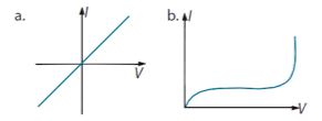 Ohmic: V and I are proportional (graph passes through origin). R is constant. (a) Non-Ohmic: V and I are not proportional (intercept). R changes. (b) |
|
5.1.10:
Derive and apply expressions for
electrical power dissipation in
resistors.
|
R=V/I
P=W/tP=I^2*RP=V^2/R hence P=IV |
|
5.2.1:
Define electromotive force (emf ).
|
Total
energy per unit charge supplied by a battery (or electrical source) around a circuit (ε = ΔEe/q OR ε
= W/q)
|
|
5.2.2:
Describe the concept of internal
resistance.
|
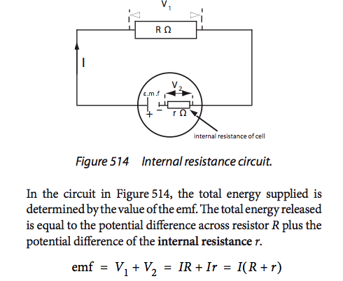 The internal resistance of the battery or electrical source (materials within device). IR = emf - Ir (terminal voltage = emf - current*internal resistance). |
|
5.2.4:
Draw circuit diagrams.
|
Appropriate symbols and drawings in Data Booklet.
|
|
5.2.5:
Describe the use of ideal ammeters
and ideal voltmeters.
|
1.
Ideal Ammeter – One
with zero internal resistance – must be placed in series in circuit. Measures current.
2.
Ideal Voltmeter – One
with infinite internal resistance – must be placed in parallel in circuit. Measures voltage.
|
|
5.2.6:
Describe a potential divider.
|
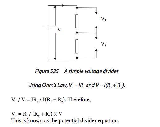 Two resistors placed in series that divide up the battery’s potential difference (R1 / R2 = V1 / V2). |
|
5.2.7: Explain the use of sensors in potential
divider circuits.
|
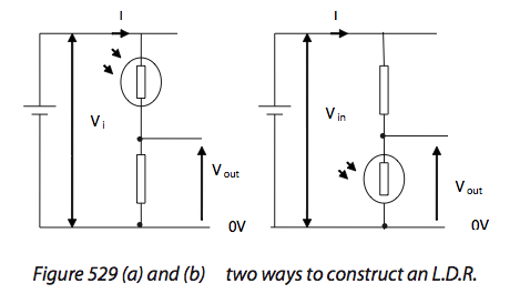 Sensors should include light-dependent resistors (LDRs), negative temperature coefficient (NTC) thermistors and strain gauges. LDR o Photo-conductive cell whose resistance changes with the intensity of the incident light. o Used in automatic cameras, smoke detectors, alarms, etc. NTC: o Change resistance with temperature. o Resistance decreases when the temperature rises; can pass more current. Strain Gauge o Strain wire becomes longer and thinner as resistance increases. o Uses a metal conducting wire that is put under vertical strain. o Wires are connected to resistance measuring devices. |
